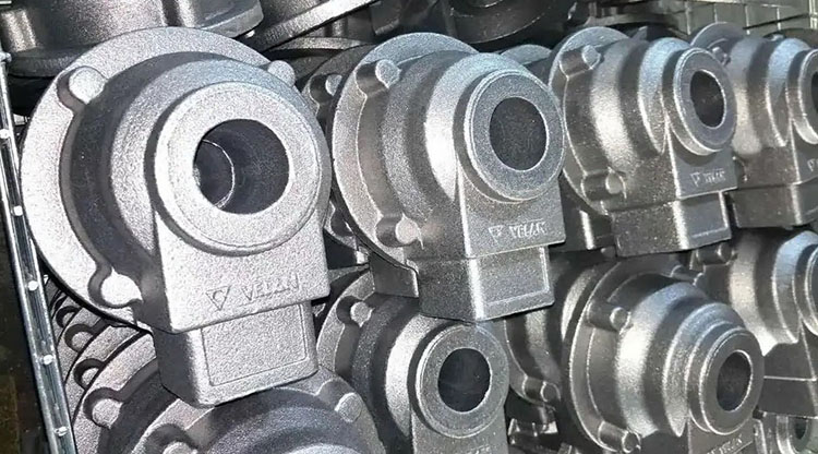
Cast iron is an early used structural material. Many parts of mechanical equipment are made of cast iron. At the same time, the repair welding of cast iron parts is still a common problem.
1 Classification of cast iron and its typical materials
Cast iron is an iron-carbon alloy with carbon content greater than 2%. It typically contains silicon, manganese, sulfur, and phosphorus as impurities. Sometimes, various alloying elements a re added to create cast iron with varying properties. Depending on the state and form of carbon present in the cast iron, cast iron can be categorized as gray cast iron, ductile iron, white cast iron, malleable cast iron, and vermicular cast iron.
2 Cast iron welding process characteristics and selection of welding materials
(1)The main problems when welding cast iron
1) Welded joints are prone to white cast iron and hardened structures. Because the weld metal cools quickly, unlike the cooling rate of cast iron in the molding sand, and some of the cast iron base metal melts into the weld, increasing the carbon content of the weld, the semi-molten zone in the heat-affected zone and the weld are prone to martensitic hardened structures, while the base metal is prone to white cast iron and other structures with poor performance.
When the weld chemical composition is cast iron, to ensure that the carbon in the cast iron precipitates as graphite and avoid the formation of white cast iron, appropriate pre-weld preheating measures should be taken to slow the weld cooling rate, adjust the weld chemical composition, enhance the weld’s graphitization ability, and prevent the carbon in the base metal from transferring into the weld and forming martensite. Whether cast iron can precipitate graphite during the cooling process depends primarily on the weld chemical composition and cooling conditions.
2) When welding cast iron, welded joints are prone to cold and hot cracking. Cold cracking typically occurs below 400°C and is caused by the combined effects of cast iron’s poor plasticity and weld restraint stress. Hot cracking, caused by low-melting-point eutectic and welding stress during crystallization, is related to sulfur content and often occurs in dissimilar weld metals using nickel-based and low-carbon steel welding consumables.
(2)Process characteristics of cast iron welding
Cast iron welding processes are generally categorized into three types: hot welding, semi-hot welding, and cold welding. Different welding processes require different welding materials.
1) Cast iron hot welding involves preheating the cast iron part, either in whole or in part, to 600-700°C and maintaining this temperature during the welding process. After welding, the part is covered with asbestos powder or other insulating material while still red-hot, and then slowly cooled to facilitate graphite precipitation. The advantage of hot welding is that it minimizes the temperature difference between the weld and the base material, thereby reducing stress levels in the weld joint, helping to prevent cracking, white spots, and hardened structures.
2) The semi-hot welding process for cast iron involves preheating the cast iron part, either entirely or partially, to 300-400°C and maintaining this temperature during the welding process. This method improves construction conditions and reduces welding costs, but it also reduces the weld’s crack resistance.
3) The cold welding process for cast iron generally does not require preheating. When the ambient temperature is low or welding constraints are severe, preheating to 100-150°C is acceptable. Cold welding of cast iron often requires the use of special welding materials and necessary process measures.
3 Selection of welding materials when welding cast iron
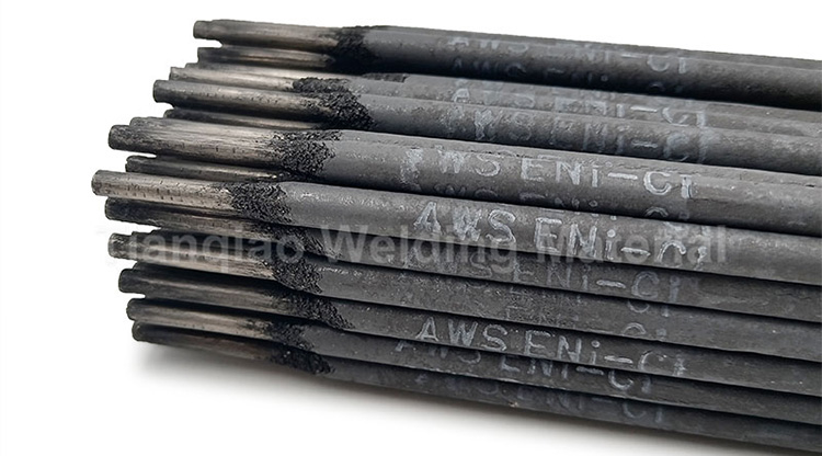
1) Cast iron hot welding and cast iron semi-hot welding can use cast iron core homogeneous welding materials, such as Z248, Z258 welding rods; or use low carbon steel core heterogeneous welding materials, such as Z100, Z208, Z238 welding rods.
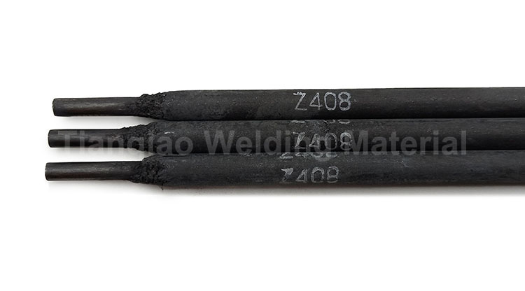
2) Cast iron cold welding generally uses heterogeneous welding materials, that is, the chemical composition of the weld is different from that of the parent material. These include three types of welding materials: steel-based, nickel-based, and copper-based. Examples include steel-based welding rods Z116 and Z117, nickel-based welding rods Z308 and Z408, and copper-based welding rod Z508.
Nickel-based welding rods have low weld hardness, a thin, intermittent white cast iron structure in the semi-molten zone, and a color similar to the cast iron base metal. They are widely used, but their production costs are high.
The Z308 welding rod has a pure nickel core and a graphite coating. The weld metal has a certain strength and plasticity. The semi-molten zone white cast iron width is only 0.05mm, allowing for machining after welding. It is primarily used for welding machined surfaces.
The Z408 welding rod has a nickel-iron alloy core and a graphite coating. The weld metal has better crack resistance than pure nickel and nickel-copper welding rods. The semi-molten zone width is 0.1mm, and the weld metal has high tensile strength.
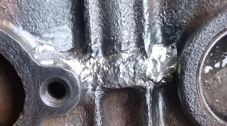
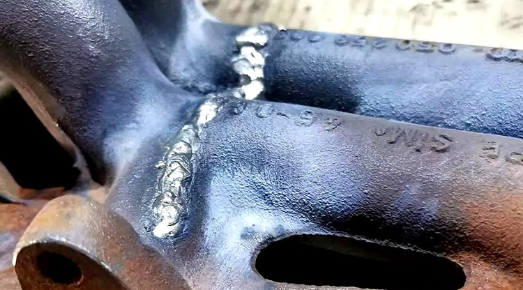
4 Cast iron cold welding repair technology and engineering application examples
(1) Common process measures for cast iron cold welding
1) Use arc welding.
2) Choose nickel-based Z308 or nickel-iron alloy Z408 welding materials.
3) Preheat to 100-150°C or not.
4) Use low heat input and narrow weld beads to reduce dilution and the width of the white layer in the semi-molten zone.
5) Reduce welding stress by adopting short-segment welding, intermittent welding, distributed welding, and hammering the weld immediately after welding.
6) Choose a reasonable welding direction and sequence. The principle of welding from areas of greater rigidity to areas of less rigidity should be adhered to. When repairing cracks, weld in sections from the end of the closed crack to the open end.
7) Use the insert welding method. This method can be used in areas with dense cracks or where the weld filler volume is large. This area can be removed and replaced with a low-carbon steel plate or other material with better weldability to change the weld distribution. 8) The wire planting method can be used on the welding groove surface, that is, drilling and tapping on the groove surface of the parent material, screwing in low-carbon steel screws, and welding with the screws as the center. This can prevent the weld from peeling off from the parent material and improve the ability to withstand impact loads. It is mostly used for repair welding of thick and large cast iron parts.
Actual cases of welding repair process for a ductile iron cement raw material mill grinding disc:
1) Drill a 12mm diameter stop hole in the direction of the crack propagation.
2) Repeatedly clean the crack area of any ore and debris with compressed air and a high-pressure water jet.
3) Using an oxyacetylene flame for heating, using a homemade gate fixture and a gear pump, reposition and reposition the crack area as much as possible, restoring the part’s apparent dimensions.
4) Prepare the outer weld groove along the crack using a carbon arc gouging process with a 70° angle and an average depth of 65mm; prepare the inner weld groove with a 40° angle and an average depth of 35mm. Use an angle grinder to remove a 3mm layer of carbon arc gouging and remove any rust within a 30mm radius around the groove, revealing the metallic luster.
5) Plant two rows of wires on each side of the outer weld groove, staggered with a spacing of 20mm. The screws are 10mm in diameter, 15mm deep, and 3mm above the groove surface. 6) Prepare several Q235 steel plate inserts, measuring 150 mm x 10 mm (width x thickness).
7) Use arc welding.
8) For weld repairs, use Z408 ф3.2 mm electrodes, dried at 200°C for 1 hour; use J507 ф3.2 mm electrodes, dried at 350°C for 2 hours.
9) Preheat before welding to a temperature T ≥ 50°C, and control the interpass temperature.
10) After wire placement, use a Z408 electrode to weld three transition layers within the outer weld groove. Each weld should be no longer than 100 mm, and no oscillation should be observed during welding.
11) Use multi-layer, multi-pass welding, with staggered overlaps and separate jump welds. Hammer the weld immediately after each pass.
12) Weld the outer groove to 1/3 of the groove depth, then complete the inner groove welding. 13) Q235 steel plate inserts were then vertically assembled and welded within the outer groove using J507 welding rods to reduce repair costs and filler volume. The outer groove was welded and the weld surface was polished smooth.
14) After welding, a surface crack inspection was performed.
The weld repair of the ductile iron cement raw mill grinding disc was completed using the above welding process. The repair passed the flaw detection inspection and is operating smoothly, meeting actual production requirements.
Post time: Sep-03-2025